
Purpose
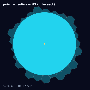
Point-radius targets — "3 miles around this store," a device ping treated as a small catchment, a platform-defined default radius around a POI — are not polygons at the source, but they become one as the first step of this conversion. Everything after buffering is the same containment machinery as arbitrary polygon to H3; this page is about getting the buffer itself right, since a wrong buffer poisons every mode downstream of it.
Source geometry and destination geometry
Source geometry is point_radius (a center coordinate plus a radius,
however specified) or device_ping when a ping is being expanded into an
uncertainty disk rather than treated as an exact point. Destination
geometry is an h3_cell_set, or a weighted crosswalk if the disk is later
intersected against multiple regions.
Exactness class
Approximate at two layered points: the disk itself is an approximation of whatever the "true" catchment shape is (real trade areas are rarely circular), and the polyfill of that disk inherits the approximation of whichever containment mode is chosen.
Containment rule and boundary behavior
The buffer step and the containment step are independent decisions:
- Buffer: construct a geodesic disk of the stated radius around the center point.
- Containment: polyfill that disk under one of the four modes —
center,full,intersect, orthreshold— exactly as documented on the arbitrary polygon page.
The buffer itself has a boundary-behavior choice that predates polyfilling: geodesic versus planar radius. A geodesic buffer measures the radius as a great-circle distance from the center, correctly accounting for Earth's curvature; a planar buffer applies the radius in a locally flat projection and is only accurate near the projection's reference latitude. At mid-latitudes over radii under 10 km the discrepancy is usually under 1%, but it grows with both latitude and radius, and a planar buffer applied at high latitude or over a multi-kilometer radius can miscalculate coverage area by several percent — always default to geodesic unless a platform explicitly executes planar circles, in which case the planar buffer should be used to match what will actually be delivered, not what is geometrically correct.
Resolution behavior
As with any polyfilled disk, higher resolution tightens the gap between the
polyfilled cell set and the true disk area for whichever containment mode is
used. Small radii interact badly with coarse resolutions: a 500-meter radius
disk polyfilled at res 6 (edge length ~3.2 km) may resolve to a single cell
under center regardless of where within that cell the true center falls,
which defeats the purpose of specifying a radius at all — resolution should
be chosen so the disk diameter spans at least several cells.
Units and CRS
Center coordinate in EPSG:4326; radius in meters, converted from any source unit (miles, feet, drive-time-derived meters) before buffering. Geodesic buffering computes distance as haversine (or a more precise geodesic formula for large radii) rather than planar Euclidean distance in degrees, which is not a distance unit at all and varies with latitude.
Algorithm
import { polygonToH3 } from "@/lib/h3/polyfill";
import { equalAreaCircle } from "@/lib/h3/circles";

// Geodesic disk buffer, then polyfill under the chosen containment mode
function pointRadiusToH3(center, radiusMeters, resolution, mode) {
  const disk = geodesicBuffer(center, radiusMeters); // polygon approximation
  return polygonToH3(disk, { resolution, mode });
}

const cells = pointRadiusToH3(storeLocation, 4828, 9, "intersect"); // 3 mi
The same conversion with the Python bindings (h3-py v4):
import h3
from shapely.geometry import Point, Polygon
from shapely.ops import transform
import pyproj

def geodesic_disk(center_lat, center_lng, radius_m, vertices=64):
    # Geodesic buffer: use an azimuthal-equidistant projection centered on
    # the point so a planar buffer of radius_m is exact at that center,
    # then reproject the ring back to lat/lng. A naive buffer in raw
    # lat/lng degrees is a planar (not geodesic) approximation and drifts
    # with latitude and radius, per the note above.
    aeqd = pyproj.CRS.from_proj4(
        f"+proj=aeqd +lat_0={center_lat} +lon_0={center_lng} +units=m"
    )
    to_aeqd = pyproj.Transformer.from_crs("EPSG:4326", aeqd, always_xy=True).transform
    to_wgs84 = pyproj.Transformer.from_crs(aeqd, "EPSG:4326", always_xy=True).transform
    disk_m = Point(0, 0).buffer(radius_m, quad_segs=vertices // 4)
    disk_deg = transform(to_wgs84, disk_m)  # back to (lng, lat) in EPSG:4326
    return [(lat, lng) for lng, lat in disk_deg.exterior.coords]  # h3-py wants (lat, lng)

def point_radius_to_h3(center_lat, center_lng, radius_m, res):
    ring = geodesic_disk(center_lat, center_lng, radius_m)
    poly = h3.LatLngPoly(ring)
    return h3.polygon_to_cells(poly, res)  # center containment only, see note

cells = point_radius_to_h3(store_lat, store_lng, 4828, 9)  # ~3 mi
h3.polygon_to_cells is center-containment only; reproducing full,
intersect, or threshold on the disk requires the same per-cell
shapely area classification shown on the
arbitrary polygon page. The tested
reference implementation for this conversion is the TypeScript in lib/.
Parameters
Center coordinate, radius (meters, after unit conversion), buffer method
(geodesic or planar), containment mode, resolution, and vertex count
used to approximate the disk polygon (more vertices reduce polygonal
approximation error at the cost of polyfill time).
Outputs
An h3_cell_set at the stated resolution and mode, or a weighted crosswalk
of (cell_id, disk_id, intersection_area, cell_coverage_fraction) rows when
the disk is being intersected against multiple downstream regions rather
than consumed on its own.
Quality metrics
coverage_ratio, overreach_ratio, and jaccard computed against the
buffered disk polygon (not the polyfilled cell set against itself) — this
isolates polyfill error from buffer error. Report the two error sources
separately: disk-polygon-vertex-count error (how well the disk approximates
a true circle) and containment-mode error (how well the cell set approximates
the disk).
Edge cases
Travel-time catchments are frequently confused with point-radius: a
"10-minute drive" catchment is not a disk at all, and forcing it through this
conversion by picking an equivalent-looking radius silently discards the
road-network shape that made the catchment meaningful — that case belongs to
a network-distance corridor, not a geodesic buffer. Platform-defined radii
(a DSP that only accepts point+radius targeting and enforces its own minimum,
e.g. 1 km) mean the caller's intended radius and the executed radius can
differ; always record both the requested and the platform-clamped radius.
Minimum-radius constraints are the sharpest edge case: many platforms refuse
radii below a floor (500 m to 1 km is common), silently clamping a smaller
request up to the floor rather than erroring — a store-specific 200-meter
catchment intended for full-mode conservatism can be executed as a
1-kilometer disk instead, changing overreach_ratio from near zero to
substantial. Always diff the requested radius against the platform's
documented minimum before treating the executed geometry as a faithful
representation of the request, and see inscribed-circle
for the reverse direction of this problem, where an H3 cell is expressed as
a platform-native point-radius target.
Assumptions and limitations
This conversion assumes the radius is a genuine Euclidean (geodesic) distance from a single center point; it is the wrong tool for irregular or directional catchments, and should not be dressed up as one by picking a radius that merely looks visually similar on a map. It also assumes the buffer step runs before any containment decision — polyfilling a raw point with a "radius" parameter passed into a polygon mode without an actual buffered polygon is not this conversion and produces undefined results.